 |
|||||||||||||||||||||||||||||||
|
|
|||||||||||||||||||||||||||||||
|
We are a proud member of |
|||||||||||||||||||||||||||||||
 |
|||||||||||||||||||||||||||||||
|
German Biogas Association |
|||||||||||||||||||||||||||||||
|
|
|
||||||||||||||||||||||||||||||||||||||||||||||||||||||||||
|
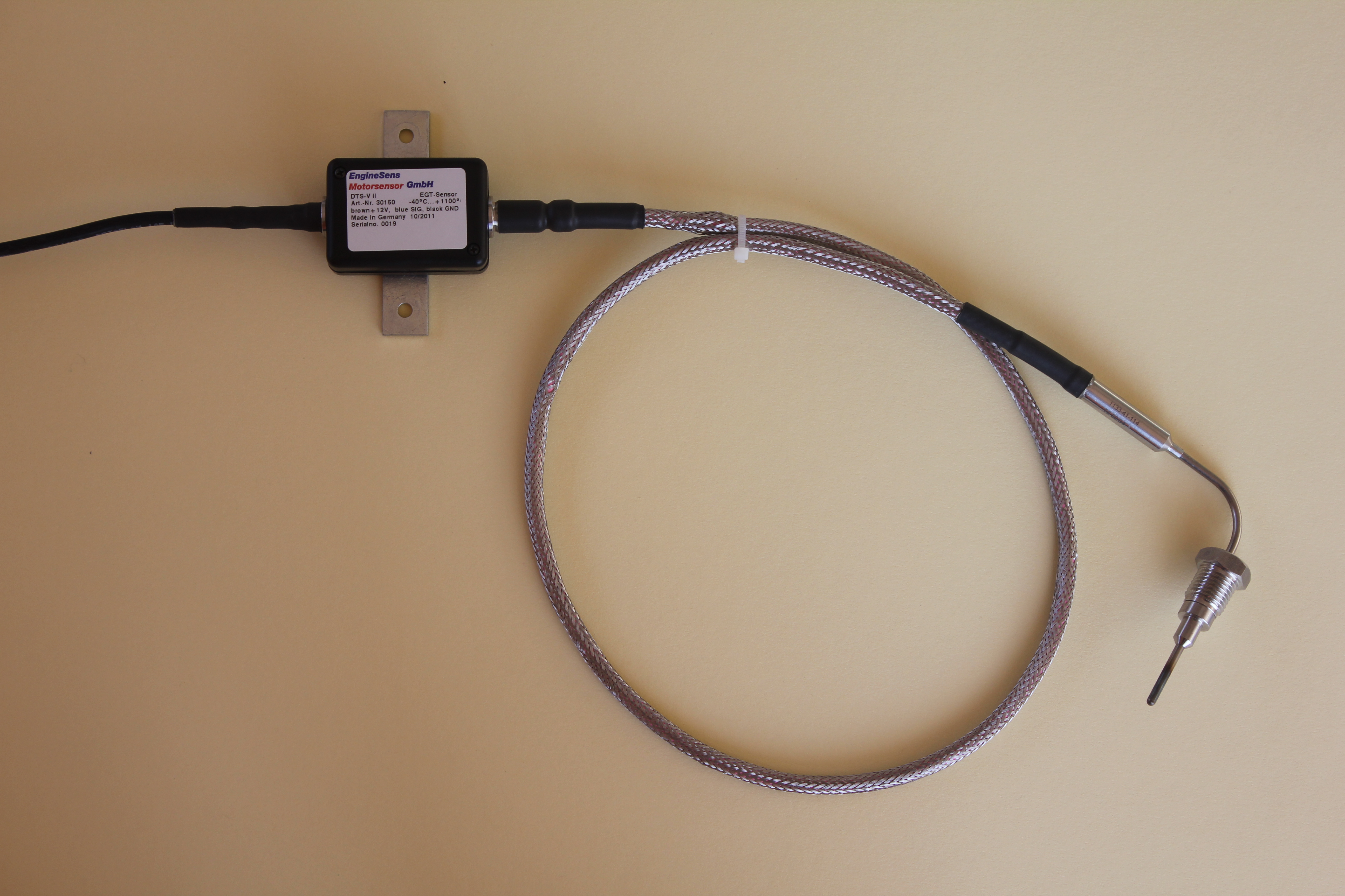
EngineSens Motorsensor distributes and manufactures in the Hessian Viernheim temperature probes and gas sensors. The following article describes the DTS-V III premium product which is produced in our company. The product itself can look back on a long tradition as a precursor by ABB Automation Products GmbH was produced until 2009 for automotive OEM. Because of lacking profitability the production was abandoned. Our house is not struggling with the overhead of a global group and continues a special version with 0-5 V DC output signal. The product has undergone major revisions to the original pattern and the result was a significantly improved response time while maintaining the proven mechanical strength. Due to the fact that the plug is not integrated in the housing, the user has more freedom to integrate own harnesses. The cable entry into the electronics housing has been substantially revised. Last but not least, the temperature range of the transmitter electronics was extended to 130 °C. A further improvement of measurement accuracy at high engine compartment temperatures and ensuring RoHs compliance were the next evolutionary steps. This is currently our best product that has no problems with the formation of microcracks due to the thermal management of vehicles and that faces no-time problems. The support sleeve design in conjunction with Inconel ™ sheath material has been proven in practice very much. It is the only product that we recommend for use at temperatures above 950 ° C in the exhaust system. The precision of +/-10 °C at 1050 ° C is unmatched. Amateur vehicle tuners might use type K-thermocouples from the next mail order shop. Those offered thermocouples are very thin and are made of regular stainless steel. They are cheap and show a certain signal drift over lifetime. A torn-off tip, which then destroys the turbocharger, changes a bargain probe in an expensive destroyer. We do not recommend using those sensors. |
|
The following text appeared in issue 9 in 2003 in the journal MTZ Engine Technology. This description of ABB highlights the peculiarities of the concept. The content has been carefully adapted by us to the current state. In addition some applications are exemplified. Exhaust Gas Temperature Probes based on Thermocouples Mostly resistance thermometers are used for monitoring the exhaust gas temperature in mass production vehicles. Thus diesel engined vehicles with particle filter and gasoline direct injection engines with stratified charge are equipped with such temperature sensors. Nevertheless monitoring temperatures by means of thermocouples offers strong advantages, which go beyond the range of applications specified before. Testbed engineers know about the advantages of thermocouples, like broad application temperature range, easy handling, highest measuring precision and short response time. As a consequence an exhaust gas temperature sensor for series application based on thermocouples has been developed. |
|
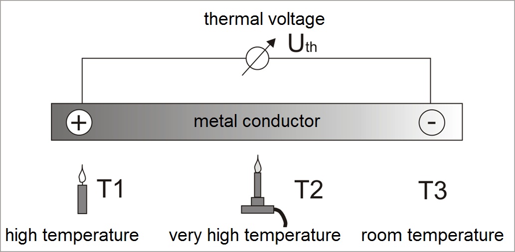
The operational principle of all thermocouples: The Seebeck Effect Temperature measurement with thermocouples is well-known since far over 150 years. It is based on the so-called "Seebeck effect". This means the fact that between the ends of a metal conductor an electric potential arises on condition that those ends are exposed to different temperatures. The temperature gradient between them is insignificant. |
|
|
|
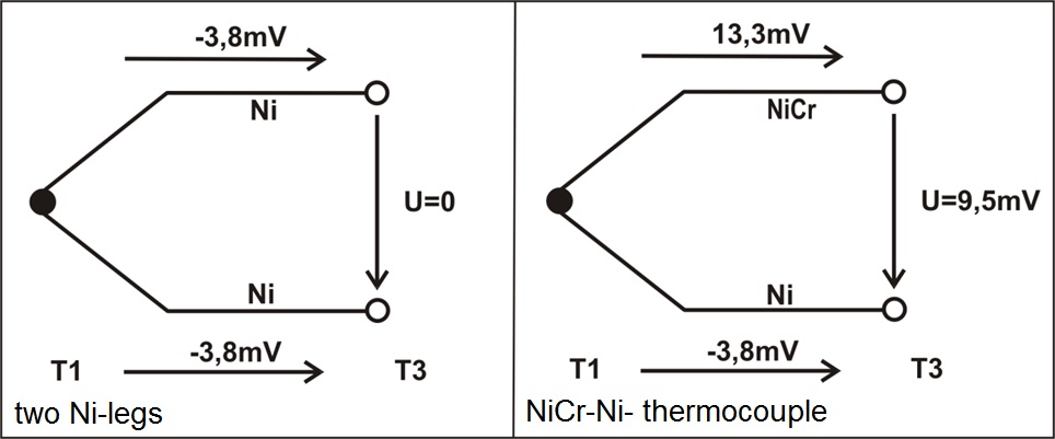
But all theory is grey: It is impossible to measure the voltage between hot and cold end of a conductor with a circuit analyser. The signal output has to be redirected from the hot edge by means of different conductors. |
|
|
|
temperature compensation. This consists mostly of a resistance temperature sensor, which determines the absolute temperature in the pick-up place of the thermovoltage. Thus the temperature at the "cold" measuring point is known as well as the temperature difference to the "hot junction", the measuring point. By both parameters the absolute temperature at the measuring point is calculated. |
|
Thermocouples in exhaust gases: The DTS-V III EngineSens developed an exhaust gas temperature sensor based on thermocouples with integrated electronics. The manufacturer indicates an accuracy of ± 10 K in the measuring range of -40 °C to 1,100 °C. This is the highest measuring precision, an exhaust gas temperature sensor achieves at present at ambient temperatures of 120°C near the transmitter. To compare: Temperature sensors with NTC (negative Temperature Coefficient) show a minimum increase of signal output in the range over 900 °C that a meaningful application is not possible. Platinum temperature sensors (PRTD) cannot withstand temperatures above 1,050°C. To avoid these inadequacies was a committed development target. The technical specification of the exhaust gas temperature sensor DTS-V III is clearly outlined:
Due to this frame it became easily clear for the development team that these characteristics are to be fulfilled with high-quality thermocouples solely. |
|
|
|
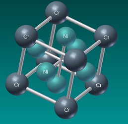
Modern material technology: Stabilization with silicon An exhaust gas temperature sensor is always exposed to highest cooling and heating rates. The k-effect was to be considered in the concept phase of the DTS-V III. EngineSens uses a procedure, with which this effect can be completely waived, without hurting thereby the positive characteristics of this type of thermocouples. For both thermowires a small quantity of silicon is alloyed. Thus the influences of the "u-condition" are almost completely eliminated. The "k-effect" is no longer provable. The exhaust thermometer DTS-V III is developed in logical consequence with a leg NiCrSi and a partner from NiSi as type "N". |
|
|
|
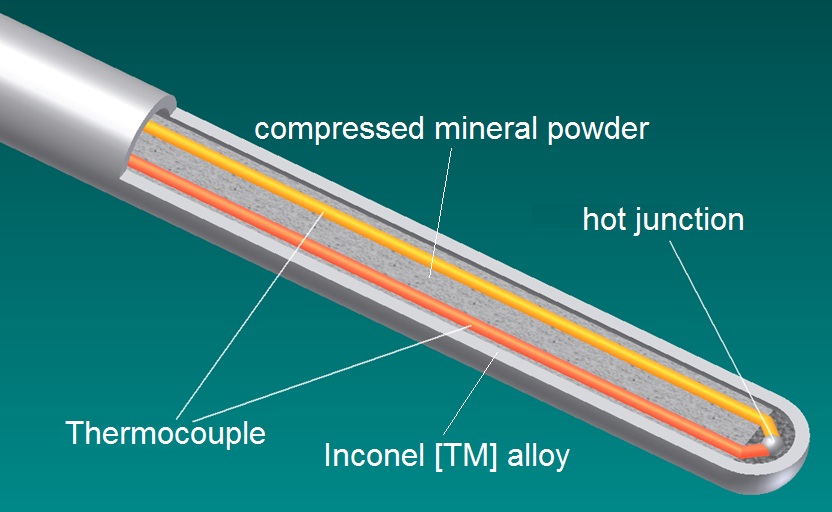
The measuring point is created by connecting the two thermowires with a welded pearl. The hot junction is sealed with a plug by mineral insulated cable, the cold side with a special epoxy resin, which short-term withstands temperatures up to 250 °C. With this structure also at high temperatures good electrical insulation values are obtained. In the exhaust system the sensor is mounted independent on position by means of a fixed sealing ring and a union nut, which locks the welding socket in the tail pipe. The position of the ring defines the immersion depth. This is variable in certain frames to optimise different applications. |
|
Linking element: the thermowire The hot junction and the comparatively "cold" electronics are linked inseparably by a shielded cable. This connection resists to extreme variations in temperature in the engine compartment and is at the same time vibration proof. The minimum bending radius is five times of its outer diameter. Electronics: High Tech signal converter An output signal can be only as precise, as the sum of all errors within the measuring chain. In order to reduce these influences from the beginning, one can further improve the system-dependent advantages of thermocouples with a high-quality signal converter. The inserted cold junction temperature compensation is based on a high-quality measuring device. The thermovoltage is converted into an analog 0.36 ... 4.89 V DC output signal. The transmitter electronics is usually installed in the engine compartment. It easily withstands the stresses ocurring there such as heat up to 130°C, moisture and vibrations. All electronic components are positioned on a PCB by means of lead-free solder. The electronics is protected by a plastic housing made of PA-66 with a high content of fiberglass. Battery voltage of 12 ... 24 V DC is the power supply. It is connected to the DTS-V by clamp 15 (ignition on). To comply with all EMC-requirements all electronic components are arranged in a special way and efficient filters are added. If the turbocharger becomes too hot With engine developers “Downsizing” is a lively discussed topic. In particular engines with smaller displacement artificial respiration is a proven tool to achieve additional torque and performance. Exhaust gases of petrol engines expose the turbine to hot gas flows up to approximately 1,000 °C. That reaches the borderline of the maximum material stress. Therefore the maximum exhaust gas temperature is a major criterion for turbo-respirated petrol engines. To protect components like exhaust manifold and charger exhaust gas temperatures over 1,000°C may not be exceeded under any circumstances during a longer period. Under usual circumstances there is a clear safety margin at which the mixture is enrichened before critical temperature values are reached. This control strategy lowers the temperature more than 150 K, preserves charger and exhaust manifold. Nevertheless this leads to a drastic degradation of fuel efficiency and exhaust gas quality by shifting the exhaust gas composition to an unfavorable conversion rate of the three-way catalyst. Assumed, a vehicle follows a truck for a longer period on single-lane road without any chance to pass. Inevitably the vehicle is moved under partial load conditions, the components temperatures are on a low level. Later results the possibility to pass, the engine’s maximum performance is now demanded. With conventionally regulated engines at higher numbers of revolutions the mixture is enrichened immediately, although the component temperatures did not heat up yet so fast that this counter measurement is necessary. Here a large clearance is given away. Engines equipped with exhaust gas temperature regulation sweep the mixture to a rich A/F-ratio if the temperature increases into critical zones. Some high sophisticated serial applications start with first counter measurements at a temperature of 950°C. This results on the one hand in an improved fuel economy and on the other hand, in a relief for the environment, since the catalyst can be operated longer under optimal conditions. This regulation is used for example in the AUDI 2.7 l Biturbo together with the ECU Motronic ME 7.1 by Bosch. This high-quality temperature monitoring system is widely to be found in vehicles automobiles of superior classes. Here the Bentley Arnage is to be named as well as AUDI RS 6, S4, RS 4, Allroad and the Bugatti Veyron. In the course downsizing engines with small displacement this regulation offers performance data of larger engines. Thus the temperature control helps 1.8 l engines to achieve higher performance in some variants of the AUDI TT and Seat Léon Cupra R. Exhaust gas values ok? - catalyst diagnosis A vehicle catalyst needs heat to start the conversion of pollutants. Since most pollutants develop during the warming-up phase of the engine, it is a goal of all exhaust gas after treatment systems to minimize the time spent until light-off. Light-off is defined as operating point which converts 50 % of the pollutants. Depending upon motor vehicle type this point is reached regarding petrol engines at approx. 300°C, regarding diesel approx. 50°C - 80°C lower. Catalyst heating measures are for example activating the secondary air pump, adjustment of spark retard at late, etc.. In order to deactivate these control strategies later, the exact knowledge of the light-off point and the current exhaust gas temperature is necessary. The DTS-VIII is in the best way suitable for this task due to high sensitivity and short response time, if it is mounted directly in catalyst proximity. If the temperature before and after catalyst is measured, the exotherm of the conversion of pollutant can be determined and a statement regarding the condition of the exhaust gas after treatment system might be derived. Petrol engines operated stoichiometrically are checked by step-response lambda sensors before and after catalyst. With stratified injection petrol engines this approach becomes more complicated. In this case it is a new approach to monitor the exotherm of a reacting start catalyst by means of temperature measurement. With this method the requirements of the on board diagnosis (OBD) can be fulfilled.
The Diesel becomes the clean man: Particle filters and exhaust gas temperature sensor State-of-the-art particulate filter systems consist of ceramics e.g. siliciumcarbide, cordierite or of sintered metal or of stamped metal foils. With all materials particles are bound to the filter with a separating rate of far more than 90 %. It is common to all that they are to be regenerated on any kind of procedure. Therefore during the operation of the engine the exhaust gas temperature is increased to approx. 550°C - 600°C until the particles adhering in the filter react with the remainder oxygen of the exhaust gas and burn down. Due to the effect of additives in the fuel the ignition temperature decreases by around 100°C, which is bought however with an increased accumulation by ash. It is a challenge to the R&D departments to increase the moderate exhaust gas temperatures of diesels to ignition temperature. A further challenge is to optimise the gas flow through the filter in such a way that a symmetric loading is guaranteed over the cross-sectional area and a constant burn-up during regeneration is ensured. Ceramic filter systems close up with increasing particle deposit from the rear to the front until the differential pressure exceeds a fixed threshold value and starts regeneration. The hot core zone ignites first and burns down into the outer zones. In average this takes about five minutes with the support of additives, without the time span doubles. If the engine is turned off during this time interval, the filter burn-up ends. Mostly then the core zone is already free, whereas the outer zones are still full of particulate agglomerates. If the engine is restarted remains the exhaust differential pressure stays under threshold value, the filter again is reloaded. It comes inevitably to an overloading of the outer zone. During the coming burn-off phases inadmissibly high temperatures of more than 1,000 °C might occur in the edge zones. The ash remainders of burned soot particles "glass" and seal the filter system perfectly. The exhaust pressure drop rises suddenly, the filter is blocked and becomes useless. How can one discover such dangerous conditions in time and seize counter measures?
A potential method consists of using in the area after the filter two highly precise temperature sensors. One probe tip is placed directly behind the core zone, the second is mounted to the outer zone. According to the temporal operational sequence during the filter burn-up the core zone sensor sees first the exotherm of the particle burn-up, then with some delay also rises the temperature in the outer region over a significant threshold value. It is possible to develop a model confirming normal regeneration. Already today temperature sensors are used to determine one of several input factors for loading models and, in addition, monitor the different process temperatures. For these tasks the particularly soot-insensitive and independent on position working sensor DTS-V III is suited due to the closed sensor tip. The already existing electronics can be adapted without large expenditures to control two sensors. |
|
|
||||||||||||||||||||
